|
Free contour |

|

|

|
|
Free contour |
|
|
|
|
To place an inner contour on the front panel via a DXF import, select the ‘Insert free contour’ function on the menu bar. In the subsequent ‘Free contour properties’ dialogue box, you can specify all the required properties. The free contour can be executed as a cut-out or as a cavity. If you have made subsequent changes to the DXF file, they can be applied immediately using the ‘Update‘ button. Detailed step-by-step instructions for the DXF import of outer and inner contours are provided here as a manual in PDF format. |
A free contour is a freely designable closed line, along which the milling cutter travels either as an outer or an inner contour:
In principle you can save as many closed lines as you like in one file. These can be inserted as free contour objects, which using the option Selection > split free contour (see further down on this page) can be broken up into a corresponding number of objects, each represented by a single closed line. |
DXF-files can be imported both in the Insert > Free contour dialog box as well as in the File > Front panel properties dialog box and then remain available for the duration of the session both for the design of the main plate outline as well as for the insertion of milling elements with free contours respectively. Use the multiselection option in the import dialog box (hold downCtrl key and click the desired DXF files one after another) to open multiple files. When you close the front panel file however, only the DXF files of the objects actually placed are stored, which will be displayed from the start when you next edit the front panel. Each of these DXF files can contain any number of closed lines (outlines), which neither cross each other nor themselves, as well as precisely one cross of short lines (e.g. 5 mm in length) as an application-specific reference point (details below under "Specification of the free contour vector graphic for the milling element"). The handling of these features depends on whether the file is used as a Main plate outline or as a milling element:
|
At present, free contour vector graphics for both the outline of the main plate as well as for a milling element can only be imported in DXF file format.
|
The following requirements must be satisfied for a vector graphic, so that it can be used to represent a milling element or create the basic shape of a main plate:
Vector graphics which do not meet these requirements will not be imported and therefore cannot be used. If an import attempt fails, a graphically supported error list is generated.
|
The user can also generate the reference point for his free contour as the junction of two additional short, mutually intersecting line segments (of, for example, 5 mm in length). The presence of such a feature is checked during import and, if necessary, is offered as an option for the reference point of the object in the properties dialog box. For further options, see the entry "Reference point" under the following heading "Free contour properties". |
After placing the object you can set the following variables for the required free contour in the properties dialog box:
|
Milling elements which contain several closed lines are automatically split immediately after they are imported and then grouped in order to keep them together. If necessary, however, the group can be split up, after which the individual elements can be edited as required, added to new groups or combined to form macro objects. If individual elements cannot be produced using the initially selected tools, for example, because the contour is too small, an automatic tool adjustment is made. The user is notified of this should this be the case. Every line can be individually assigned to a tool. Tip: Every free contour element that is split can be selected directly by pressing Ctrl + left mouse button without breaking up the group. |
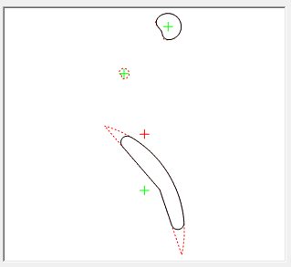
Due to the finite diameter of a milling tool, intended and achievable free contours – especially with small internal radii or narrow aperture angles - do not match in all circumstances. Differences can be discerned in the preview window in that the original contour is shown as a red dashed line in addition to the free contour that can actually be produced. This allows you to readily see that certain contours, for example, are completely ignored if they are too small or the tool is too large.
Alternatively, differences can be discerned, e.g., typing Ctrl + d to toggle between full and outline mode . The choice of a smaller diameter for the tool will always lead to a better approximation at the positions in question. Please note that additional costs are incurred for a tool change as well as for longer milling times (when using a smaller tool diameter). For certain necessary features - for example, a corner with an inner radius of zero - you can continue to work with an additional drilled hole or for right angles also by placing a rectangle. These additional milling elements are then each placed before the free contour is milled. |
In individual cases, when Front Panel Designer is updated, a free contour that was loaded with an older version of program is produced differently owing to error corrections made in Front Panel Designer. The user will be notified in such cases when the file is loaded. The presentation of the free contour is saved to the FPD file and is typically not recalculated. In the case described above, you can enforce this by selecting View → Clear DXF Preview in the menu. |