|
Scaling |

|

|

|
|
Scaling |
|
|
|
|
You can edit the geometric properties of one or more selected objects both with the Selection > Change size dialog box as well as with the mouse, by dragging the access points associated with the object either in or out. |
Scaling an object refers here to a change in its geometric dimensions or its size. Production-related threshold values must be complied with (e.g. a rectangular cutout cannot be narrower than the smallest diameter among the multitude of available tools). The number of degrees of freedom available for scaling is dependent upon different constraints:
|
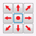
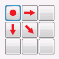
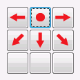
An anchor point must be set for the scaling of a placed object, i.e. that point of the object which remains "anchored" with the main plate during scaling and thereby is the only point to "survive" the procedure without being displaced. When scaling is executed by dragging the mouse from one of the access points displayed (4 or 8 points), the point opposite the grabbed point is anchored. However, by simultaneously pressing the Shift key, the reference point of the object will always be anchored. When scaling from the modification dialog box however, you can select one of nine anchor points directly. |
An object can be scaled using the mouse, by grabbing one of the 4 or 8 marked access points on the rectangular outline of the selected object with the mouse and dragging this in or out while holding the left mouse button. While doing so the opposite access point is in principle the anchor point. If you additionally keep Shift pressed however, the reference point of the object becomes the anchor point. In addition, a non-rotationally symmetrical object, while simultaneously pressing Ctrl , is scaled while maintaining its proportions or aspect ratios. This measure is unnecessary for rotationally symmetrical objects, since their aspect ratios are maintained anyway. Ctrl and Shift can be used independently of each other. During the scaling process the coordinates of the cursor are shown in the Status bar .
|
After marking the object (or objects) the command Selection > Change size… opens the Resizing dialog box. In this dialog box, you can 1) adjust the anchor point and 2) specify the new size, either in absolute terms, or make this change in a defined step or by selecting a percentage.
|