|
Edge machining |

|

|

|
|
Edge machining |
|
|
|
|
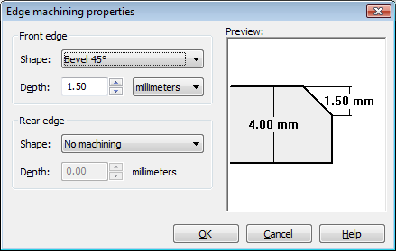
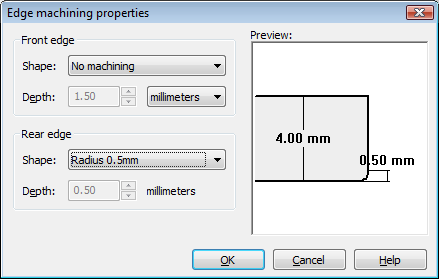
Both edges of a front panel can optionally be produced with a circumferential bevel (30°, 45° or 60° with variable depths) or with circumferential rounding (radius 0.5 to 3mm). The corresponding dialog box is opened with the Edge machiningbutton. The edges of the milling elements can incidentally also be circumferentially beveled or rounded. |
Edge machining is possible without exception for all basic shapes of front panel, regardless of their width, height, and thickness:
For a rectangular front panel, the edge is machined taking the set corner radii into account. With a free contour, the edge resulting from processing is machined (particularly with small inner radii or narrow aperture angles, this can deviate from the geometrically defined contour). |
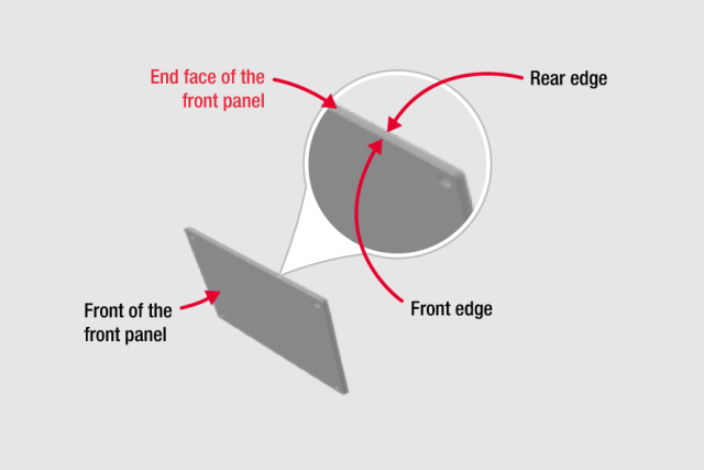
Both edges, the
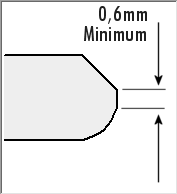
can be machined independently of each other. The sum of the bevel depths or rounding radii is only limited by the thickness of the panel, while the program ensures that a 0.6 mm strip remains unmachined on the end face of the front panel (see "Requirements for the remaining end face" below). The default setting for both edges is "no machining". |
The front and rear edges of the front panel can be produced independently of each other either beveled (beveled cavity) or rounded (quarter circle). Select the desired option from the drop-down list assigned to the respective edge (default setting in each case is "no machining").
Intermittent bevels or rounding (only machining certain sections of the circumferential edge) on request. |
A machined edge is "bright". If the appearance of the machined front edge is to match the appearance of the visible base area, then you have the possibility of having your front panel subsequently anodized or powder coated. |
Both the type (bevel or rounding) as well as the depth or radius of the machining, can in principle be set independently or combined for both edges. However, for manufacturing reasons, the program ensures that an unmachined area with a width of at least 0.6 mm remains on the end face. This allows the front panel to be held in a frame with 0.4 mm "lugs" clamping it in place throughout the machining process.
If the input value is lower, a corresponding error message is triggered and the input can only be completed or saved after the depth(s) have been accordingly reduced or adjusted. |
|
|